
DQ Resistor Series
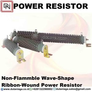
Ribbon-Wound Power Resistors (DQ) Introduction
(DQ) Wave-shape ribbon-wound power resistor design neutralizes inductance parasitoid
Power Wave-Shape Ribwound Resistor supports the use of numerous taps, has low impedance, and can be fabricated in various shapes to support a wide range of applications. The DQ Series is RoHS compliant and lead free. For custom specifications, or order individual replacement units, entire grids with various mounting configurations, please contact us to discuss the details.
Construction:
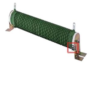
- A tubular ceramic has two terminals, and is wound with a resistance element consisting of a wave-shaped alloy ribbon.
- Terminal bands are spot welded after installation on the core and then a resistance-alloy ribbon wire is crimped and edgewound onto the core.
- Non-flammable resin insulation is applied after cooling and drying through a temperature process and then the component mounts are attached.
- The resistance value range is relatively low due to alloy material limitations; see the DR series if upper resistance values required.
Features :
- Fixed, tapped styles, or adjustable type are available.
- Special terminals are available for unusual applications.
- Special tolerances, temperature coefficients, and resistance value can be specified.
- Ayrton Perry type non-inductive winding formats are available. See DQS Series when requied.
- Standard resistance tolerance is H(±3%), J(±5%) and K(±10%). Closer tolerances are available upon request.
- The wire is spot welded to the terminal bands and then "fastened" onto the core with a silicone, cement, or vitreous enamel coating.
- Standard lug terminals available with or without terminal hardware. Single and double quick connect terminals can be specified.
- DQ Series Design allows for efficient heat dissipation at higher temperature ranges so the resistor is half the physical size of an equivalent rated roundwire resistor.
Applications :
- The Power Ribwound DQ Series is suitable for educational modeling applications, load testing,
- industrial machinery resistor, electric power distribution resistors, instruments, automation control installations,
- lift trucks, overhead cranes, elevator resistors, arc and spot welders, battery charger resistors, machine tools, conveyor resistors, and UPS systems.
DQS 75W ~ 2000W
 |
|
| Wattage Rating |
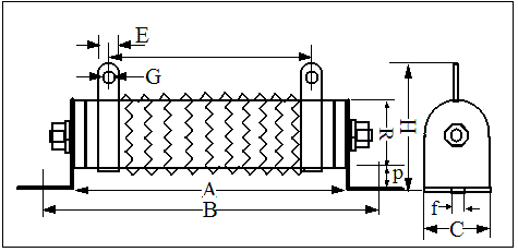
Dimensions (mm) | Max. Resistance Value(Ω) |
|||||||||||||
| A | B | C | D | E | F | G | H | I | J | K | L | M | O | ||
| 75W | 110 | 25 | 16 | 30 | 8 | 150 | 5 | 18 | 6 | 166 | 58 | 1.2 | 6 | 27 | 0.1~8Ω |
| 90W | 90 | 28 | 18 | 32 | 8 | 130 | 5 | 19 | 6 | 146 | 60 | 1.2 | 6 | 27 | 0.1~9Ω |
| 120W | 110 | 28 | 18 | 32 | 8 | 150 | 5 | 19 | 6 | 166 | 60 | 1.2 | 6 | 27 | 0.1~12Ω |
| 150W | 140 | 28 | 18 | 32 | 8 | 180 | 5 | 19 | 6 | 196 | 60 | 1.2 | 6 | 27 | 0.1~15Ω |
| 180W | 160 | 28 | 18 | 32 | 8 | 200 | 5 | 19 | 6 | 216 | 60 | 1.2 | 6 | 27 | 0.1~18Ω |
| 225W | 195 | 28 | 18 | 32 | 8 | 235 | 5 | 19 | 6 | 251 | 60 | 1.2 | 6 | 27 | 0.1~23Ω |
| 240W | 185 | 35 | 24 | 36 | 10 | 225 | 5 | 19 | 8 | 245 | 76 | 1.6 | 6 | 34 | 0.1~24Ω |
| 300W | 210 | 35 | 24 | 36 | 10 | 250 | 5 | 19 | 8 | 274 | 76 | 1.6 | 6 | 34 | 0.3~30Ω |
| 375W | 210 | 40 | 25 | 38 | 12 | 250 | 5 | 20 | 8 | 274 | 78 | 1.6 | 6 | 34 | 0.3~38Ω |
| 450W | 260 | 40 | 25 | 38 | 12 | 300 | 5 | 20 | 8 | 320 | 78 | 1.6 | 6 | 34 | 0.3~45Ω |
| 600W | 330 | 40 | 25 | 38 | 12 | 370 | 5 | 20 | 8 | 395 | 78 | 1.6 | 6 | 34 | 0.3~60Ω |
| 750W | 330 | 50 | 35 | 50 | 12 | 380 | 6 | 25 | 9 | 400 | 100 | 1.6 | 8 | 40 | 0.3~75Ω |
| 900W | 400 | 50 | 35 | 50 | 12 | 450 | 6 | 25 | 9 | 470 | 100 | 1.6 | 8 | 40 | 0.3~90Ω |
| 1000W | 460 | 50 | 35 | 50 | 12 | 510 | 6 | 25 | 9 | 530 | 100 | 1.6 | 8 | 40 | 0.5~100Ω |
| 1200W | 460 | 60 | 40 | 55 | 15 | 515 | 6 | 30 | 10 | 535 | 110 | 1.6 | 10 | 50 | 0.5~120Ω |
| 1500W | 540 | 60 | 40 | 55 | 15 | 595 | 6 | 30 | 10 | 615 | 110 | 1.6 | 10 | 50 | 0.5~150Ω |
| 2000W | 650 | 65 | 42 | 62 | 15 | 702 | 6 | 30 | 10 | 722 | 115 | 1.6 | 10 | 50 | 0.5~200Ω |
Specification - DQS Series
| Test Item | Test Methods | Characteristics |
| Resistance tolerance | JIS-C-5202 5-1 | Resistance |
| Temperature coefficient | JIS-C-5202 5-2 | ±400PPM/°C MAX |
| Load rating | JIS-C-5202 5-4 | ΔR/R≤ ±(0.5%+0.1Ω) Surface temperature up 350°C MAX |
| Short-term overload | JIS-C-5202 5-5 500% rated wattage 5 seconds |
Free of appearance or structural irregularity ΔR/R≤ ±(2%+0.1Ω) |
| Insulation resistance | JIS-C-5202 5-6 500VDC | 100MΩ min |
| Dielectric withstanding voltage | JIS-C-5202 5-7 1000VDC 1 minute Between terminal and anchor stand |
Free of appearance or structural irregularity ΔR/R≤ ±(0.1%+0.05Ω) |
| Terminal strength | JIS-C-5202 6-1 8kg 30 seconds | Free of appearance or structural irregularity |
| Vibration | JIS-C-5202 6-3 1.5m/m 10 ~ 50 ~ 10 Hz/min X-Y-Z 2 hours each |
Free of appearance or structural irregularity Surface coating crack ΔR/R≤ ±(1%+0.05Ω) |
| Thermal shock | JIS-C-5202 7-3 Room temp 30 minutes ON-55°C 15 minutes OFF |
Free of structural irregularity ΔR/R≤ ±(1%+0.05Ω) |
| Humidity | JIS-C-5202 7-5 40°C 90%RH 240 hours |
Free of appearance or structural irregularity Surface coating crack ΔR/R≤ ±(3%+0.1Ω) |
| Load life | JIS-C-5202 7-10 90 minutes ON - 30 minutes OFF500 hours |
Free of appearance or structural irregularity Surface coating crack ΔR/R≤ ±(5%+0.1Ω) |
| Flame retardation | JIS-C-5202 7-13-3-2 100% - 600% rated wattage load |
US UL-94 flame retardation test V-0 grade noncombustible |
| REMARKS: | 1. Resistance and resistance tolerance were tested in-house with micro resistance meter. 2. Coating refers to UL-certified data provided by supplier |
|